A servo system diagram is a diagram that shows the connection between the PLC, driver, servo motor, and feedback devices in the motion control system. Understanding the diagram correctly helps engineers install quickly, operate stably, and troubleshoot effectively. This article by XINJE will help you understand the concept, structure, and important notes when working with servo system diagrams.
What is a servo system diagram?
In the field of automation, a servo system diagram is a drawing that shows the connections and interactions between the main components in a servo control system.
This is a visual tool that helps engineers and technicians understand how the signal and electrical currents move in the system, from the controller (PLC), driver, to the servo motor and feedback devices.
Depending on the purpose of use, the servo diagram can be presented in many different forms:
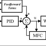
- Block Diagram: Shows the main functional blocks of the system in the control – feedback sequence. Easy to use in introductory documents or technical training.
- Wiring Diagram: Describes in detail the signal wires, power wires, connection pins between PLC – Driver – Servo Motor – Encoder – Sensor. This is the most used diagram in actual installation.
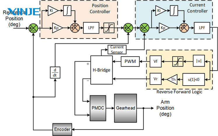
- Signal Flow Diagram: Is a diagram that focuses on the direction of control and feedback signals. Helps engineers program and troubleshoot quickly.
What are the main components in a servo system diagram?
A servo system diagram is not simply a drawing of connections between devices, but also clearly shows the roles and relationships between the core components of a precision motion control system. Below are the components that often appear in a standard servo system diagram:
- Controller (Controller / PLC): This is the “brain” of the entire system. The programmable controller (PLC) or HMI will send control signals to the servo driver based on the pre-installed operating program.
- Actuator (Servo Driver / Amplifier): The servo driver receives control signals from the PLC, then amplifies and converts this signal into a suitable electrical form to supply to the servo motor.
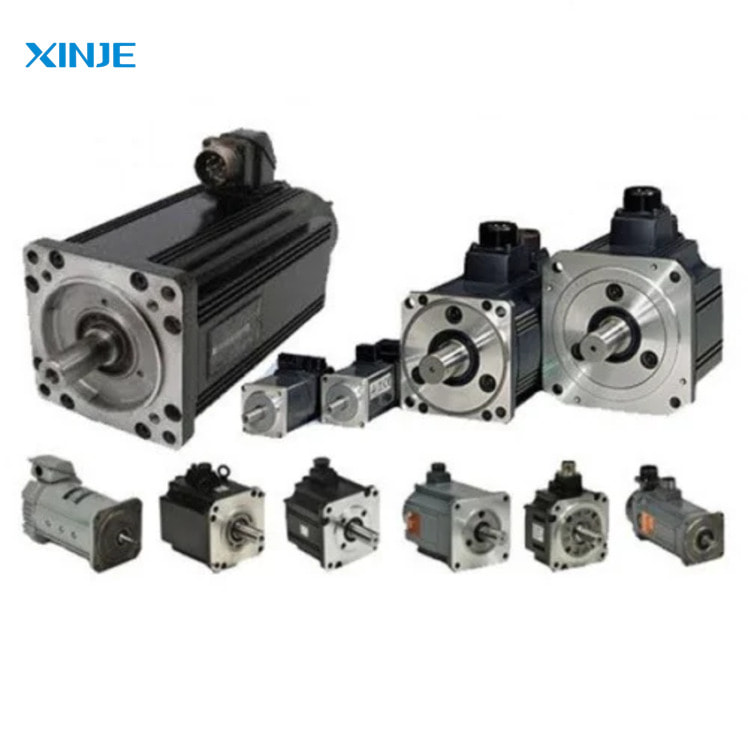
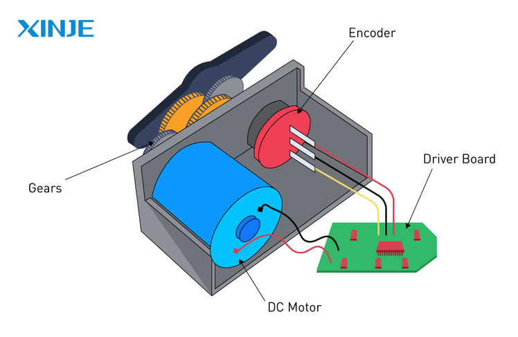
- Servo motor: This is a device that creates precise mechanical motion. Servo motor operates based on the signal from the driver and responds to position information through the encoder.
- Position feedback unit (Encoder / Resolver): Encoder is often integrated in the servo motor, helping to record the position, speed, rotation direction of the motor shaft and send feedback signals to the driver.
What are the benefits of the Diagram Servo System for businesses?
Using the servo system diagram – servo system diagram – not only helps to clearly visualize the system structure but also brings many practical benefits in the design, construction and operation process.
- Support for accurate system design and implementation from the beginning: Diagram helps engineers easily determine the number of devices needed, how to connect between PLC – driver – motor – encoder – sensor. Minimize errors in the installation stage, avoid confusing signal pins or power sources.
- Save time: Clear diagrams help technicians quickly identify the location of each connection port, I/O signal, power supply. No need to waste time looking up individual device manuals.
- Easy maintenance and troubleshooting: When the system has an error (for example, the motor does not rotate, loses feedback from the encoder, etc.), the diagram helps to quickly localize the location that needs to be checked. Limit unnecessary disassembly or widespread inspection.
- Optimize servo system performance: Correctly understanding the system diagram helps engineers configure the optimal driver/motor for each specific application. Increase accuracy, stability of movement, reduce power consumption.
What are the things to consider when choosing a Servo System Diagram?
Choosing a suitable servo system diagram not only helps the system operate properly but also avoids errors that cause equipment damage or incorrect operation. Below are the factors that need special attention when choosing a servo system diagram for practical applications:
- Suitable for the type of equipment being used: Driver and motor must be of the same brand or compatible with the connection standard. What type of PLC is the controller? Does it support communication protocols such as Modbus, EtherCAT, CANopen?
- Check the number of axes and required control functions: Use a 1-axis, 2-axis or synchronous multi-axis servo? Do you need to control position, velocity or torque?
- Make sure to clearly show the control and feedback signal flow: Signal direction: from PLC → driver → motor → encoder feedback to driver. The location of the sensor and limit switch in the diagram must also be clearly illustrated.
- Correct with the voltage and power standard at the factory: Does the servo use a single-phase or three-phase power source? Is the voltage 220VAC or 380VAC? If the diagram is not correct with the voltage standard, it can cause short circuits in the equipment or driver power errors.
In which fields is the Servo System Diagram commonly applied?
The Servo System Diagram is not only a technical reference document but also a powerful support tool in many practical activities in factories, production workshops, and automation lines. Understanding and proficiently using the servo system diagram brings high efficiency in the following fields:
- Application in the installation of motion control systems: Electrical – control engineers rely on the diagram to connect PLC, driver and motor correctly. The diagram helps determine the direction of connection of control signals, power cords, and feedback ports from the encoder.
- Application in maintenance and repair of servo systems: When the system has an error: loss of encoder feedback, servo not running, travel limit is activated by mistake… then the diagram is the “error finding map”.
- Application in training technical staff: For large manufacturing enterprises, training new technicians based on the servo system diagram is the most effective way. Personnel can visualize the entire control and feedback flow in the system.
Conclusion
Understanding and using the servo system diagram correctly not only helps the system operate accurately and stably, but also saves time, costs and minimizes technical risks throughout the entire life cycle of a production line.
This is a powerful support tool for electrical and automation engineers, from the design, installation to maintenance and expansion of the system.
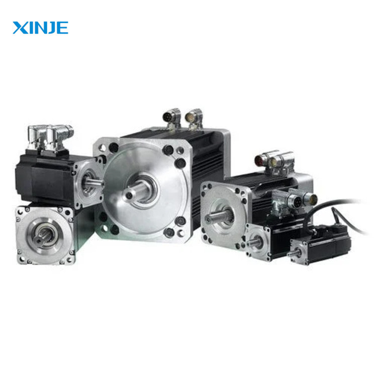
At XINJE, we provide a complete set of servo solutions (motor, driver, PLC…) with advice on appropriate connection diagrams for each practical application. If you need support in building a servo system diagram or looking for genuine – quality – ready-to-use servo equipment, do not hesitate to contact our technical team today.